Our Solutions
TRAINING & SUPPORT
Login to the Amphenol Broadband Resource Portal for pre- and post-deployment support.
Login
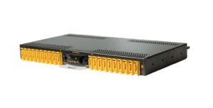
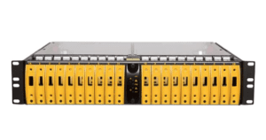
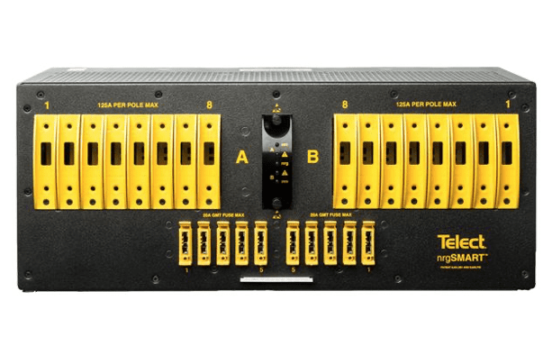
Amphenol Network Solutions’ nrg600BT08-M 600A dual-feed 8/8 circuit breaker/TFD Load Center with 5 GMTs features -48V operating voltage to fit in legacy and “next-gen” network applications. The advanced circuit level monitoring is engineered into a 4 RU footprint.
| Inputs | |
| Voltage range, nominal voltage | -40V to -60V (nominal -48 VDC) |
| Max. input load rating | 600A per side at max |
| Short circuit withstand rating | 5000A |
| Nominal power loss at full load | Less than 75W per side @ 28.000W full load per side (600A x 48V) |
| Percentage of full power dissipation at nominal voltage |
Less than 1% |
| Max. input interrupt device | 750A |
| Input terminal studs (with nuts, flat washers and spring washers) for dual-hole compression lugs |
• Two pair of 3/8-16 studs on 1 in. centers per terminal (max lug width of 1.94 in. [49.2 mm]) per pair • Torque nut (using 9/16 in. or 15 mm wrench) to 150 in./lb. (~17 N m), max. |
| Input wire size | #1 AWG to 750 MCM |
| Dual-Hole Outputs | |
| Max. output single-pole, long-delay circuit breaker (ea.) |
100A |
| Max. output TPC, TPS, or TLS | 125A |
| Max. output load (ea) – continuous | 100A |
| Minimum short circuit interrupt rating | 5000A |
| Output terminal studs (with KEPS, nuts, and washers) for dual-hole compression lugs |
• 1/4-20 studs on 5/8 in. centers (max. lug width of 0.680 in. [15.8 mm] for a BATT terminal and 0.70 in. [17.7 mm] for a RETURN terminal) • Torque bolts (using 7/16 in. or 12 mm wrench) to 50 in./lb. (~5.5 N m), max. |
| Output wire size | #14 AWG minimum |
| GMT Outputs | |
| Max. GMT output fuse (ea) | 20A |
| Max. GMT output load (ea) continuous | 14A |
| GMT output terminals for compression lugs | • 10, remvable, #6-32 panhead screws (max. lug width of 0.29 in. [7.4 mm]) • Torque to 6.3 in./lb. (~0.7 N m), max. |
| GMT output wire size | #22 AWG to #12 AWG, depending on output fuse rating |
| Dry Contact Alarms | |
| Alarm wire size | #22 to #18 AWG |
| Alarm terminals | Wire-wrap |
| Relay contact ratings | Dry Form-C contacts (1A @ 30 VDC, 0.5A @ 60 VDC, 0.3A @ 125 VAC) |
| Max. Alarm Power Rating | @ 24V: 72 mA (1.73W) @ 48V: 147 mA (7.06W) |
| Grounding | |
| Earth GND terminal bolts (with washers) for dual-hole compression lugs |
• Two pair of 1/4-20 threaded holes on 5/8 in. centers • Torque bolts (using 7/16 in. or 12 mm wrench) to 50 in./lb. (5.5 N•m), max |
| Ground wire size | #2 AWG recommended |
| Voltage Sensor | |
| Sensor Accuracy | 0 to -19.99V: ±0.3V, -20V to -60V: ±0.1V |
| Voltage Measurement Range | 0 to -60 VDC |
| Feed Voltage Detection | 0 to -19.99V: Alarm, -20V to -60V: Normal |
| NOTE: • Voltage measurement may be slightly different than at input terminal blocks due to the voltage drop within the panel. • Sensors are factory calibrated and do not require user adjustment |
|
| Communication | |
| nrgNET sensor and alarm card power | -18 VDC nominal |
| nrgNET data communication | RS-485 |
| nrgNET connector | Removable 5-pin connector with screw down terminals |
| nrgNet connector functions | nrgNET IN from the nrgCONTROL or nrgSMART panel, nrgNET OUT to next inline nrgSMART panel |
| Supported protocols | Proprietary nrgNET used to communicate between panels and controller |
| Fit and Finish | |
| Material | 14-gauge Steel |
| Color | Pewter grey powder coat |
| Mechanical | |
| Dimensions (L x W x H) | 12″ x 17.25″ x 7″ |
| Rack Space | 4 RU |
| Environmental | |
| Operating temperature | -5ºC to 55ºC |
| Humidity | 0 to 90%, non-condensing |
| Weight (approximate) | |
| Installed | 47 lbs. (21.3 kg) |
| Shipping | 49.1 lbs. (22.3 kg) |
| Warranty • Standard one-year warranty on all parts • The warranty is extended through the addition of the annual maintenance and support contract (nrgSMART-APSC) |
|