
1RU 325A DUAL-FEED, 8/8 CIRCUIT BREAKER PANEL

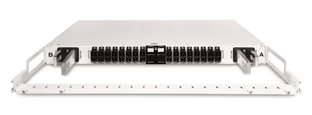
Require Density?   Connectorization provides a dense solution, allowing outputs to come straight out of the panel, so that a 1RU panel truly takes only 1RU; no open space is required below the panel for cable routing.

Need to Streamline Your Install?   Connector contacts use the same installation crimpers as standard lugs, and quickly plug into the power panel with a dual-locking retainer.  Connectors can be dis-assembled and re-assembled in the field.  Screw terminations are eliminated, making installation and upgrades very fast.  Pre-assembled whips can be custom-ordered to allow even faster deployments.

Have a Variety of Capacity Requirements?   Panels are available in high current input 8×8 circuit breaker or TPA fuses, mid-current TPA/circuit breaker/GMT combinations, and low current 10×10 GMT and 15×15 GMT variations.

Need Some Power Intel?   Panels are available with standard alarming via output contacts or with nrgSMART per-circuit current monitoring.

Love the Simple Life?   All panels have removable alarm cards for easy field servicing.  All standard panels share a common alarm card and all nrgSMART panels share a common nrgSMART alarm card, making spare inventory simpler to manage.

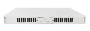
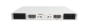
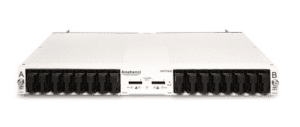
This platform provides front access to alarm enable/disable switch configuration for uninstalled breaker locations. Also featured are front LED indicators for power/breaker alarms, monitoring status, rear connections for form C relay alarms, and optional nrgSMART connections. Each of the 325A feeds provide power for up to eight output positions. Field replaceable circuit breakers are available from 5A to 60A per position. The front of the panel features a faceplate designed to protect against unintended breaker on or off switching. The panel supports universal voltages (±12VDC to ±48VDC).

Primary Benefits

  • Universal voltage (±12VDC, ±24VDC, and ±48VDC) enables standardization on a single part number for multiple voltages
  • Up to 60A breakers for distribution to a variety of network elements
  • UL and NEBS compliant to ensure industry-standard safety and functional requirements
  • Form C relay contacts provide reliable alarm connections
  • Integrated designation cardholder for simple circuit identification
  • Fail alarm LEDs indicate breaker and power failures
  • Clear, flame-retardant polycarbonate cover (94V-0) protects input and output power connections and wiring from damage
  • Either vertical feed inputs and staggered output terminal blocks to facilitate waterfall cable management, horizontal feed inputs and output connectors that speed-up installation and allow cables to exit straight back from the panel, or vertical feed inputs and output connectors that allow input cables to be routed directly from above and speed up installation of outputs
  • Optional Individual Circuit Monitoring provides high accuracy, 100% passive monitoring
  • Collect voltage and current for both feed and output circuit
  • Collect temperature using optional nrgTEMP probes

Features:

Specifications

Inputs: Specifications:
Voltage range (nominal voltage) ±12VDC, ±24VDC and ±48VDC
Max. input load rating 325A (continuous) @ 45°C per panel (De-rated to 200A @ 70°C
Short circuit withstand rating 5000A
Nominal power loss at full load Less than 45W per side @14,400W full load per side (325A x 48V); 325A @ 45°C per panel (De-rated to 200A @ 70°C)
Percentage of full power dissipation at nominal voltage Less than 0.5%
Max. input interrupt device 125% of panel rating (for 325A rated feeds)
Optional (Standard and -SC Versions): Vertical input terminal studs (with Keps nuts and flat washers) for dual-hole compression lugs Two pairs of 3/8-16 studs on 1″ centers per terminal [max. lug width of 1.15″ (29.2 mm)]. Torque nut (using 9/16″ or 15 mm socket) to 150 in/lb. (~17 N•m), max.
Optional (-C Versions): Horizontal input terminal landings (with Keps nuts, flat washers, and bolts) for dual-hole compression lugs Two pairs of 3/8″ holes on 5/8″-1″ centers per terminal [max. lug width of 1.5″ (38.1 mm)]. Torque bolt (using 9/16″ or 15 mm socket) to 150 in/lb. (~17 N•m), max.
Input wire size 2/0 AWG to 350 MCM
Grounding: Specifications:
Earth GND terminal bolts (with washers) for dual-hole compression lug Three sets of 1/4-20 threaded holes on 5/8″ centers. [max. lug width of .50″ (12.7 mm)]. Torque bolts (using 7/16″ or 12 mm socket) to 50 in/lb. (5.5 N•m), max.
Ground wire size #14 AWG to #4 AWG
Outputs: Specifications:
Output circuit breaker Single-pole: 60A
Output load Single-pole: 48A continuous
Minimum short circuit interrupt rating 5000A
Optional (Standard Versions): Terminal blocks, single-hole compression lugs 16, #10-32 screws [max. lug width of .50″ (12.7)]. Torque screw to 20 in/lb. (2.3 N•m), max.
Optional (Standard Versions): Output wire size, single-hole compression lug #14 AWG to #4 AWG
Optional (-C and -SC Versions): Connectors (purchased separately) 16, P40 connector plugs, latching, safe touch
Optional (-C and -SC Versions): Output wire size, connectors #12 AWG to #6 AWG
Circuit breakers AIRPAX 1U Series
Alarms Specifications
Alarm relay contacts 2A @ 30 VDC; 0.6A @ 60 VDC
Max. alarm card power rating @12V: 18mA (0.22W) @24V: 20mA (0.48W); @48V: 30mA (1.44W)
Alarm wire size #24 AWG, typical (#26 to #20 AWG)
Alarm terminals Wire wrap or mates with TE Connectivity 3-640428-3
Dimensions: Specifications:
300CB08/nrg300CB08 Height: 1.75″ (44mm)

Depth: 13.0″ (331 mm)

Width: 17″ (432 mm) without brackets

19″ and 23″ brackets included with panel

300CB08-C/nrg300CB08-C Height: 1.75″ (44 mm)

Depth: 18.8″ (478 mm) without tie bar

            22.0″ (559 mm) with tie bar

Width: 17″ (432 mm) without brackets

19″ and 23″ brackets included with panel

Tie bar included with panel

Cable-end connectors not included with panel

300CB08-SC/nrg300CB08-SC Height: 1.75″ (44 mm)

Depth: 13.0″ (331 mm) without tie bar

            16.5″ (420 mm) with tie bar

Width: 17″ (432 mm) without brackets

19″ and 23″ brackets included with panel

Tie bar and cable-end connectors not included with panel

Compliance: Specifications:
UL Listed
NEBS Level 3
Voltage Sensor (nrgSMART model only): Specifications:
Sensor accuracy -19.99 to +19.99V: ± 0.3V

-20V to -60V: ± 0.1V

+20V to +60V: ± 0.1V

Voltage measurement range -60 to +60 VDC
NOTE:

  • Voltage measurement may be slightly different than at input terminal blocks due to the voltage drop within the panel
  • Sensors are factory calibrated and do not require user adjustment
Current Sensor (nrgSMART model only): Specifications:
Precision/accuracy ±5% precision, ±0.25A accuracy

Example: 40A current, will measure 40A ± (40A*5%) ± 0.25A

= 40A ± 2.0A ± 0.25A

=37.75A to 42.25A

Communication (nrgSMART model only): Specifications:
nrgOS minimum required version nrgOS 4.1.0
nrgNET communication protocol Proprietary serial protocol used to communicate between panels and controller
nrgNET connector Removable 5-pin connector with screw-down terminals
nrgNET connector functions nrgNET IN from the Controller or upstream nrgSMART panel nrgNET OUT to downstream nrgSMART panel

Sign up for our newsletter:

Sign Up

For more information:

Contact Us